
Home > Products > Thermocouples & RTDs > View All Configurations

Thermal Corporation’s complete product line of Thermocouples and RTDs
Our Thermocouple and RTD configurations list includes plastic probes, refractory probes, and thermocouple extensions.
Ready to order? Click here to request a quote for a Thermocouple or RTD by selecting the desired product from the Select a Product drop-down.
| Thermocouple Configuration / RTD Configuration & Description | Configuration Diagram | ||||||||||||
|---|---|---|---|---|---|---|---|---|---|---|---|---|---|
| Configuration 200 / RTD Configuration 800 General Purpose Plastic Probe Straight Tip and Spade Terminal, Stainless Steel Hose | 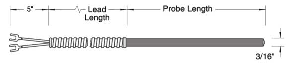 |
||||||||||||
| Configuration 201 / RTD Configuration 801 General Purpose Plastic Probe Straight Tip and Plug Terminal, Stainless Steel Hose |  |
||||||||||||
| Configuration 202 / RTD Configuration 802 General Purpose Plastic Probe 90° Bend and Spade Terminals, Stainless Steel Hose | 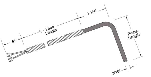 |
||||||||||||
| Configuration 203 / RTD Configuration 803 General Purpose Plastic Probe 90° Bend and Plug Terminals, Stainless Steel Hose | 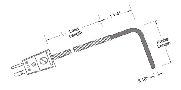 |
||||||||||||
| Configuration 204 / RTD Configuration 804 General Purpose Plastic Probe Straight 1/8″ Diameter Probe and Spade Terminal | 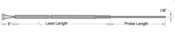 |
||||||||||||
| Configuration 205 / RTD Configuration 805 General Purpose Plastic Probe Straight 1/8″ Diameter Probe with Male Plug | 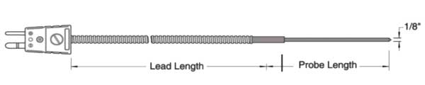 |
||||||||||||
| Configuration 206 / RTD Configuration 806 Fixed Bayonet Plastic Probe Straight Probe and Spade Terminal, Stainless Steel Hose, Spring Loaded with Lock-nut Minimum Probe Length: 1 3/4" | 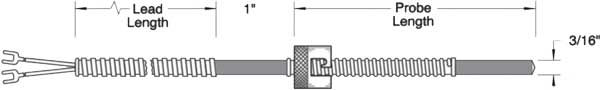 |
||||||||||||
| Configuration 207 / RTD Configuration 807 Fixed Bayonet Plastic Probe Straight Probe and Plug Terminal, Stainless Steel Hose, Spring Loaded with Lock-nut Minimum Probe Length: 1 3/4" | 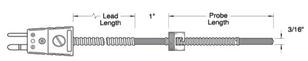 |
||||||||||||
| Configuration 208 / RTD Configuration 808 Fixed Bayonet Plastic Probe 45° Bend and Spade Terminal, Stainless Steel Hose, Spring Loaded Lock-nut Minimum Probe Length: 1 3/4" | 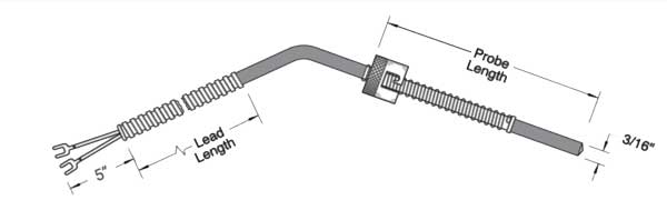 |
||||||||||||
| Configuration 209 / RTD Configuration 809 Fixed Bayonet Plastic Probe 45° Bend and Plug Terminal, Stainless Steel Hose, Spring Loaded Lock-nut Minimum Probe Length: 1 3/4" | 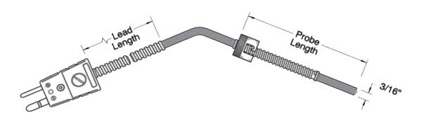 |
||||||||||||
| Configuration 210 / RTD Configuration 810 Fixed Bayonet Plastic Probe 90° Bend and Spade Terminal, Stainless Steel Hose, Spring Loaded Lock-nut Minimum Probe Length: 1 3/4" | 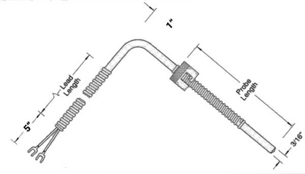 |
||||||||||||
| Configuration 211 / RTD Configuration 811 Fixed Bayonet Plastic Probe 90° Bend and Plug Terminal Minimum Probe Length: 1 3/4" | 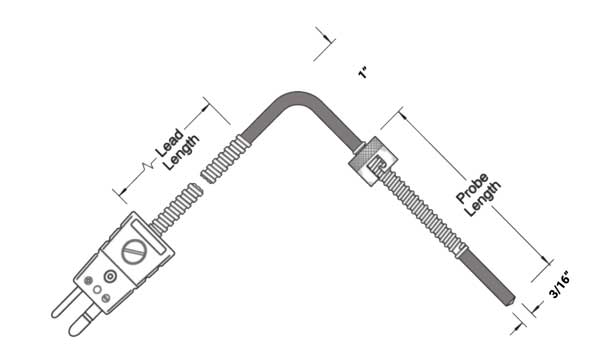 |
||||||||||||
| Configuration 212 / RTD Configuration 812 Universal Bayonet Plastic Probe Stainless Steel Hose and Spade Terminal, Adjustable Lock-nut | 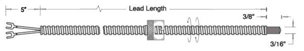 |
||||||||||||
| Configuration 213 / RTD Configuration 813 Universal Bayonet Plastic Probe Stainless Steel Hose and Plug Terminal, Adjustable Lock-nut | 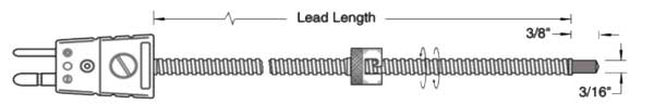 |
||||||||||||
| Configuration 214 / RTD Configuration 814 Universal Bayonet Plastic Probe Stainless Steel Overbraid and Spade Terminals, with 8″ Spring, 12″ Spring also available, Adjustable Lock-nut. | 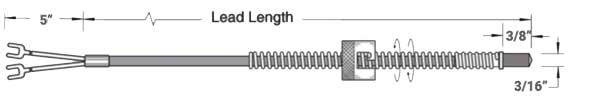 |
||||||||||||
| Configuration 215 / RTD Configuration 815 Universal Bayonet Plastic Probe Stainless Steel Overbraid and Plug Terminal, with 8″ Spring, 12″ Spring also available, Adjustable Lock-nut. |  |
||||||||||||
| Configuration 216 / RTD Configuration 816 Nozzle Plastic Probe With Stainless Steel Overbraid, Hex Bolt & Spade Terminal Available Bolt Sizes: | 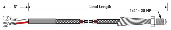 |
||||||||||||
| Configuration 217 / RTD Configuration 817 Nozzle Plastic Probe with Plug With Stainless Steel Overbraid, Hex Bolt & Plug Terminal Available Bolt Sizes: | 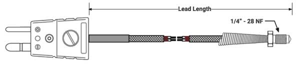 |
||||||||||||
| Configuration 220 / RTD Configuration 820 Extruder Plastic Probe With 4″ Flexible Lead and Plug Terminal. Probe bodies are stocked in 3″ and 6″ lengths. Other lengths available. | 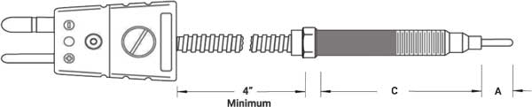 |
||||||||||||
| Configuration 221 / RTD Configuration 821 Extruder Plastic Probe With Rigid Lead and Plug Terminal. Probe bodies are stocked in 3″and 6″ lengths. Other lengths available. | 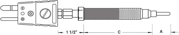 |
||||||||||||
| Configuration 222 Refractory MI Probe Refractory insulated thermocouple with flexible stainless steel leads and spade terminals. | 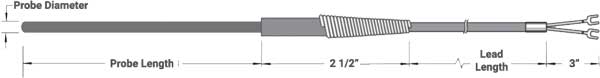 |
||||||||||||
| Configuration 223 Refractory MI Probe Refractory insulated thermocouple with flexible stainless steel leads and plug terminal. | 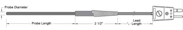 |
||||||||||||
| Configuration 224 Refractory MI Probe Refractory insulated thermocouple with terminal plug. | 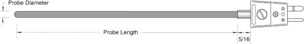 |
||||||||||||
| Configuration 225 / RTD Configuration 825 Refractory MI Probe Refractory insulated thermocouple with cast aluminum head. Available Option of 1/2″ x 1/2″ NPT Fitting. | 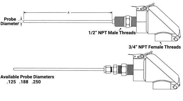 |
||||||||||||
| Configuration 226 Refractory MI Probe Refractory insulated thermocouple replacement probe. | 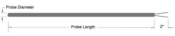 |
||||||||||||
| Configuration 227 Underbolt Plastic Probe Nickel-Plated Copper Ring Terminal, Stainless Steel Overbraid and Spade Terminal. | 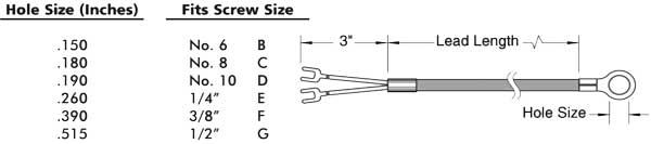 |
||||||||||||
| Configuration 228 Underbolt Plastic Probe Nickel-Plated Copper Ring Terminal, Stainless Steel Overbraid and Plug Terminal. | 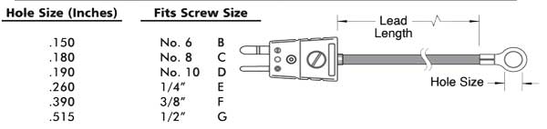 |
||||||||||||
| Configuration 229 / RTD Configuration 829 General Purpose Plastic Probe General purpose probe with Straight Tip, Stainless Steel Overbraid on leads and Spade Terminal. Also available with Plug. | 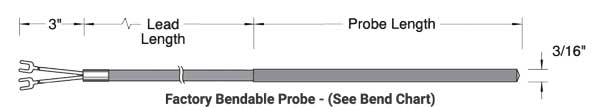 |
||||||||||||
| Configuration 250 Bayonet Adapter Used to convert 1/8″ diameter probes to bayonet probes. Adapter is slipped onto the probe and located at the desired position, then the nut is tightened to permanently attach the adapter at that location. Part #: CPN 8027 | 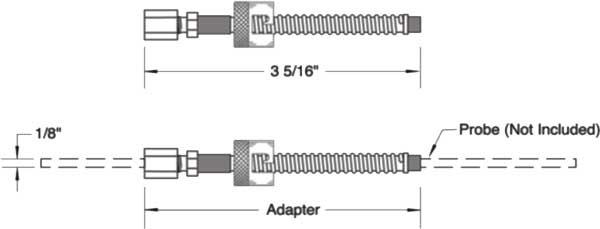 |
||||||||||||
| Configuration 253 Thermocouple Extension Thermocouple Extension with Stainless Steel Flexible Hose, Spade Terminals on One End and Plug Terminal on Other End | 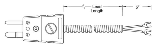 |
||||||||||||
| Configuration 254 Thermocouple Extension Thermocouple Extension with Stainless Steel Hose, Spade Terminals on One End and Jack on Other End | 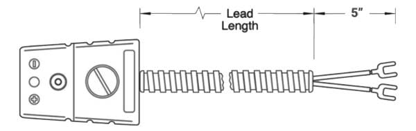 |
||||||||||||
| Configuration 255 Thermocouple Extension Thermocouple Extension with Stainless Steel Flexible Hose, Jack on One End and Plug Terminal on Other End | 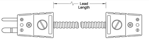 |
||||||||||||
| Configuration 258 Thermocouple Extension Thermocouple Extension with Stainless Steel Overbraid with Jack on One End and Plug Terminal on Other End | 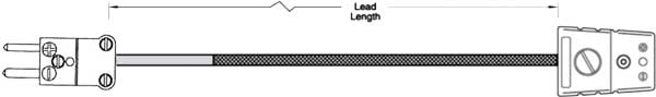 |
||||||||||||
| Configuration 259 Thermocouple Extension Thermocouple Extension with Stainless Steel Overbraid and Spade Terminals at Both Ends | 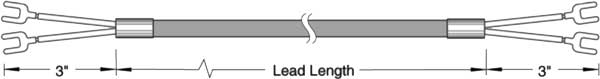 |
||||||||||||
| Configuration 261 Shimstock Thermocouple Brass or Stainless Steel Shim Stock Thermocouple with Stainless Steel Overbraid Leads. | 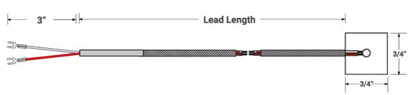 |
||||||||||||
| Configuration 262 Clamp Type Thermocouple Clamp Style with Stainless Steel Overbraid
| 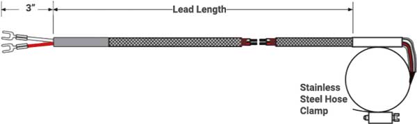 |
||||||||||||
*Discounts May Apply. Call for Discounts Based on Order Quantity. |
|||||||||||||
Written by Shelby Reece
Date Published: 09.24.2018
Last Updated: 03.11.2020