Why We Urge to Avoid Contamination of Industrial Heaters
This video topic focuses on why it is so important to make sure that your heaters do not get contaminated by substances. Contamination causes industrial heaters, like this ceramic band heater, to fail very quickly and have an extremely short heater life.
Related Blog Posts on Extending Heater Life
We have several blog posts that go into more detail on how to extend the life of specific types of industrial heaters like cartridge heaters, mica band heaters, and strip heaters. If you are interested in checking them out, they are listed below:
The Differences Between Band Heaters: Mica Bands vs Ceramic Bands
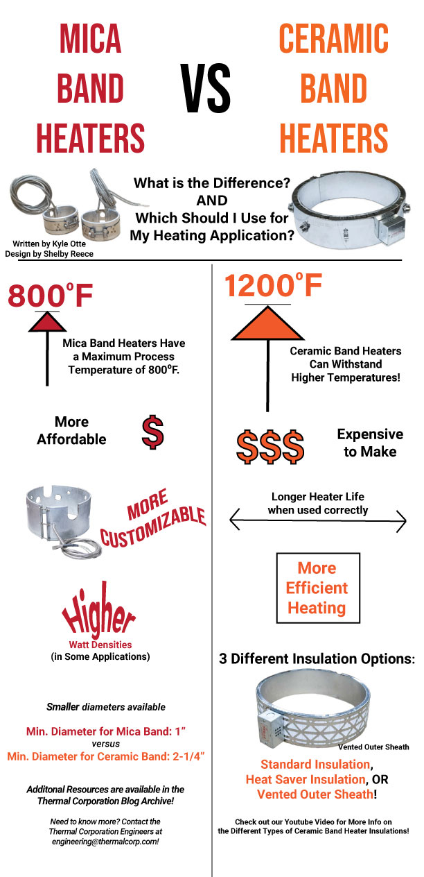
There are two types of band heaters that Thermal Corporation manufactures: mica band heaters and ceramic band heaters. There are strong points with each type, and the general differences are laid out below:
Temperatures
Ceramic band heaters can withstand a higher temperature than mica band heaters. Ceramic band heaters have a maximum operating temperature of 1200⁰F vs a maximum operating temperature of 800⁰F for a mica band heater.
Heater Life
Ceramic band heaters typically (but not always) have a longer life expectancy. This is due to the coiled resistance wire that is fed through ceramic blocks (called knuckles) vs. the thin resistance ribbon that is used in mica band heaters. The coiled resistance wire has a smaller ratio of surface area to internal cross-sectional area and thus doesn’t really oxidize and burn through as fast as the ribbon.
Watt Density
Mica band heaters can have a higher watt density than ceramic band heaters. Because the resistance ribbon in a mica band heater is tightly clamped between pieces of mica, there is better heat transfer from the ribbon to the exterior surfaces of the heater. Also, in general, mica band heaters will have less unheated area than a ceramic band heater, especially in smaller band heaters.
Customizability
Mica sheets can be cut into custom shapes and sizes, whereas ceramic band heaters are limited by the size of the knuckles. Because of this, mica band heaters are also much more customizable when it comes to dimensions. Ceramic band heaters are limited to 1/2″ width increments, whereas mica band heaters can be any width within the upper and lower limits of at least 1″ by 1″, depending on the specific mica band configuration.
Pricing
Ceramic band heaters are more expensive than mica bands. The ceramic knuckles are quite expensive when compared to the thin sheets of mica that mica bands are constructed from. However, this difference may be compensated for by the increased efficiency of the ceramic band heater.
Insulation Options
Standard ceramic band heaters have one layer of 3/8″ thick ceramic paper insulation over the knuckles, and then a stainless-steel outer sheath that reflects heat back into the process. The “Heat Saver” ceramic band insulation option has one layer of 1/8″ thick ceramic paper topped with a reflective stainless-steel sheath, and then an additional 2 layers of 3/8″ thick paper, topped by an additional sheath. All of this insulation yields a higher efficiency heater vs. a mica band heater. Ceramic band heaters also offer a “Vented Outer Sheath” option, seen in the image below. This allows heat to escape from the process, if needed for your application.
Closing Remarks
In conclusion, you just need to examine your heating process and specific needs for a band heater and decide between a mica band heater or a ceramic band heater. If we can be of any assistance, please let us know. Mica bands are cheaper, can have higher watt density, and are more easily customizable. Ceramic bands are more efficient, can withstand higher temperature, and generally last longer.
I once worked with a customer that manufactured flexible fishing lures. They had two set-ups for creating the lures- an old system and a new system. The two systems were virtually identical except for the fact that the newer system, for which they purchased a band heater, heated up too slowly.
Initially, I was led to believe that they were using a two-piece mica band heater. If they had been using a two-piece heater, I would have suspected that the heater was wired incorrectly. There are two ways to verify this.
Two Ways to Determine if a Two-Piece Heater is Wired Incorrectly
Measure the voltage across each heater half. The voltage on each half should match the stamp on the heater. This particular heater was a 120V heater. So for this case, they should both have read 120V. If 60V was read, then the heaters were wired in series rather than in parallel. This is a common issue we see. (See our blog post on “Should Your Heaters Be Wired in Parallel or in Series?” for more information on this topic.) If the voltage is half of the correct voltage, the wattage output will be 25% of the stamped wattage.
Visually inspect the wiring. One terminal, or lead, of each heater half should be tied to the black 120V wiring. The other end of the heater half should be connected to the “white” neutral wiring.
If the heaters measured the correct voltage, what would you check next?
Turn off the power and disconnect the power leads going to one end and measure the resistance of each heater half. The resistance should be approximately: R = V2 / W
In this case, the voltage (V) was 120V, and the wattage (W) was 1500W as stamped on the heater.
HOWEVER, I found out that this was a one-piece heater and not a two-piece heater. Therefore, what should I check first? If you said, the heater resistance, then you are correct. Before I made this measurement, I asked the following question: Was the LED light on the controller ON all the time?
Why did I ask this question?
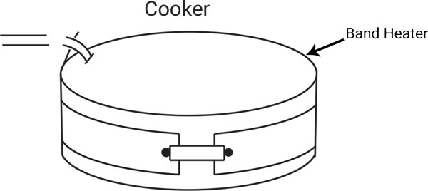
The light was ON all the time. If the light was not ON all the time, then the heater was not turned on the entire time as the process heated. This would indicate a possible programming error with the temperature controller. When I talked to a technician at the customer’s plant, it was mentioned that the temperature controller indicated that the temperature quickly went to 380°F, but the actual process took about 20 to 30 minutes to get hot. I asked the customer to describe the process in more detail. What would I see if I was at the plant looking at the process?
The Heating Process
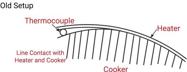
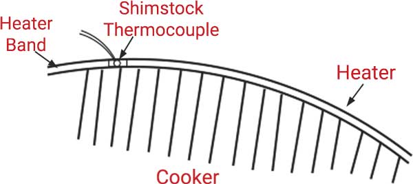
The heating process was described to me as such: the heater and thermocouples were covered in fiberglass. On the older system, a thermocouple probe is slipped under the edge of the heater. On the new system, a shimstock thermocouple is slipped under the edge of the heater. The thermocouple probe only has one line contact with the heater and the cooker, like this diagram:
Who knows for sure what was being measured?
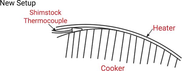
Now that the customer is using a shimstock thermocouple, it might look like this:
It may very well be that the shimstock thermocouple is primarily measuring the heater temperature. In any case, both of these configurations are very poor setups.
The Thermal Corporation Recommendation
We recommended that they place the shimstock thermocouple in the heater gap, up against the cooker. Then, place some high-temperature insulation on top of the thermocouple so when the band is tightened, the strap screw would push the thermocouple up against the cooker securely. This ensures the temperature sensor is measuring the cooker temperature, not just the temperature of the heater.
After these changes were applied to the customer’s process, it corrected their problem, and looked something like this:
Written by Jim Dixon and Shelby Reece Edited by Kyle Otte Date Published: 11.05.2019 Last Updated: 11.05.2019
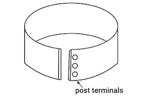
A customer ordered a mica band configuration 528 that was 9.55 inches in diameter and 1.5 inches wide. The heater was rated at 2,000W, 480V. The customer asked that the post terminals be moved so an incorporated strap could be used.
The application required that the heater have 1/2″ nickel return ribbon and an extra layer of mica inside the heater. The recommended wattage was 1,200W, yet the customer ordered a 2,000W heater. The customer called in and mentioned that the heater glowed orange hot and he wasn’t sure why. Immediately, I knew this was because the heater was getting well over 1,000 degrees F. But, why? See the diagram below.
The first thing I suspected was watt density. Watt density is calculated as follows: Heated Width = 1-1/2″ – 1/4″ – 1/4″ = 1″ Heated Length = 29-1/4″ – 1-7/8″ = 27-3/8″ Heated Area = 1″ x 27-3/8″ = 27-3/8″ in2 Watt Density = 2,000W / 27-3/8 in2 = 73 Watts/in2
This is about twice what it should be! This is why it was orange hot, but what can we do to fix this issue? There are two options: A. Increase Heated Area B. Reduce Wattage This is how I handled it:
I asked the customer about possibly increasing width. The customer said we could go to 1-3/4″ wide. We also talked about possibly converting to a configuration 500 heater which would remove the 1-7/8″ circumference length used for the post terminals. This would also remove the 1/2″ nickel return ribbon and a layer of sandwich mica.
I, then, asked the customer how they came up with 2,000W for their quoted heater. The customer said that this was the wattage on a ceramic band heater they had used in that place beforehand. This did not line up, however, because ceramic band heaters start to fail around 40 Watts/in2.
My next question surrounded whether the customer was using PID control and he said yes. I asked him to measure the on-time and off-time and calculate the percentage of time the heater was on, using this formula: on-time / (on-time + off-time) He calculated 75%. I asked him if that was the exact calculated number or if he had read it off of the control panel. He, then, told me that he was able to set it to any percent he desired. That was my AHA!-moment. This was not PID Control, it was a percentage timer. He thought he was able to operate on even less! 75% of 2,000W is 1,500W.
After all of our discussion, the customer decided to try a similar-style heater with a 1-3/4″ width and 1,500W. The heated area would now be: Heated Width = 1-3/4″ – 1/4″ – 1/4″ = 1-1/4″ Heated Area = 1-1/4″ x 29-1/4″ = 35.56 in2 Watt Density = 1,500W / 36.56 in2 = 41 Watts/in2 This heater is much better than the first iteration of this heater. We provided the updated heater and the customer had no more problems.
Written by Jim Dixon Edited by Shelby Reece and Kyle Otte Date Published: 10.31.2019 Last Updated: 11.01.2019
We had a call from a customer questioning how to calculate what the current would be for each wire in 3-phase band heater. Here is the band heater breakdown: 480V, 3,000W, 3-phase. The heater looked something like the diagram you see below.
Inside this heater, it was wired in a “wye” configuration. The wye configuration wiring diagram would look like:
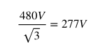
The resistance of each winding card inside the heater is equal, giving us a balanced load. Therefore, each phase will handle 1/3 of the load. 1/3 of 3,000W is 1,000W. 480V is the voltage between the 3 phases (line to line). The voltage between any phase and the ground (line to ground) is:
Now that we know the wattage and voltage in each leg of the 3-phase power, we can calculate the current.
Current = Watts / Volts = 1,000W / 277V = 3.6 Amps in each leg
Was This Case Study Helpful?
Let us know! We will continue to post more case studies offering solutions to your questions on different industrial heating applications.
Have a different question?
Did this post not answer your question? Contact our engineers and we will be happy to answer any questions you have regarding industrial heaters, applications, or industrial heating technology! Shoot us an email, phone call, or instant chat message now!
Written by Jim Dixon Edited by Shelby Reece and Kyle Otte Date Published: 10.07.2019 Last Updated: 10.08.2019
In this video, Kyle Otte gives some tips on how to extend the life of your Thermal Corporation band heater. These tips include those such as: handling the band heater with care, avoiding excessive cycling, and process temperature limits for both mica bands and ceramic bands.
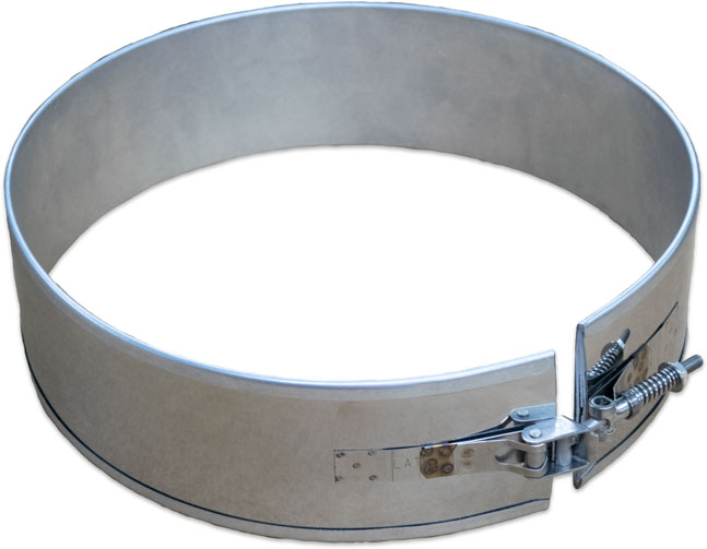
The mica band heater used in this video features our NEW! Latch and Trunnion Closure System! For more information about our latch and trunnion option for band heaters, read our blog post!
To request a quote for a mica band heater, click here! Direct any questions you have to our customer service department by phone at (800) 633-2962, by email at sales@thermalcorp.com, or by using our instant chat feature located at the bottom of the page.
We often get questions from customers asking us how to find the correct measurement of a band heater when sending in a quote for an order. Kyle Otte, an engineer at Thermal Corporation, explains how to measure a mica band heater in this video blog below!
Have any other questions?
Are you still a little confused on how to get the correct measurements, or have a related question? Contact our engineers and they will be happy to assist you! The Engineering Department contact information is below for your convenience.
A few weeks ago, we published a blog post and sent out an email to our subscribers about a new band heater option: the Monel sheath. Thermal Corporation is proud to announce a second new band heater option this Fall. We can now manufacture our high temperature mica band heaters with a latch and trunnion closure system attached to the heater! We have had several customers request this option in the past, and once again we, at Thermal Corporation, have listened.
Latch and Trunnion Closure System
A latch and trunnion closure system allows for quick closing of a heater and eliminates the time consuming process of starting a bolt into a threaded barrel nut. Once the latch is secured, a nut is tightened against a spring, which provides a constant closing force even as the band heater expands on startup.
Construction of a Latch and Trunnion
Our technicians begin construction by using a stainless steel outer sheath and welding stainless steel tabs onto the sheath. This gives us the ability to roll the heater before we attach the latch and trunnion system. This is an important step in making the heater the appropriate diameter per the customer’s specifications. The latch and trunnion is too bulky to go through the rolling process, thus it must be attached once the band is already rounded.
Direct Questions to Our Technicians
Our technicians can answer any questions you have about this new option. Contact our band heater product technician, Matt Blackburn, by email at matt.b@thermalcorp.com or by phone at (800) 633-2962 x153.
Future Options
What would you, as our customer, like to see offered next? Any suggestions for a product or option that you would like to see us start offering in the near future can be directed to our sales and customer service department. Thank you and we appreciate your business!
Written by Kyle Otte and Shelby Reece Edited by TC Marketing Team Date Published: 08.16.2019 Last Updated: 08.16.2019
Monel Option Now Available for Thermal Corporation Band Heaters
You Asked, We Listened!
Thermal Corporation is now offering a new option for our mica band heaters — sheaths and straps made from Monel material!
What is Monel?
Monel is an alloy that is primarily composed of nickel and copper. It also contains small amounts of iron, manganese, carbon, and silicone. Monel’s appearance is similar to that of stainless steel. Because of its resistance to corrosion and acids, Monel is often used in caustic atmospheres.
Several of our Thermal Corporation customers have requested band heaters with Monel sheath. And we listened! Thermal Corporation can now make band heater sheaths, both inner and outer, out of Monel! We can also use the Monel material to construct band heater straps.
Interested in More Information Regarding This New Option?
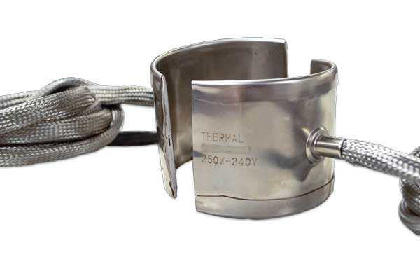
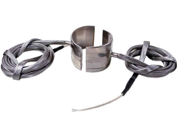
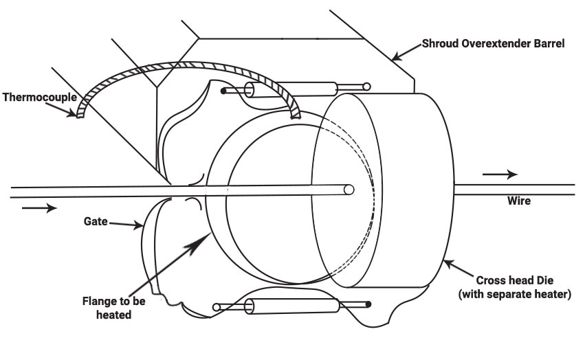
A customer phoned our engineering department here at Thermal Corporation complaining that he was experiencing very poor life with a mica band heater– a life of only one week! He explained that the application was to heat a flange that was attached to a gate at the end of an extruder. The extruder was adding a layer of nylon to wire-in cross-head die. The flange sat between the gate and the cross-head die. (The cross-head die had its own separate heater.) The flange also had a thermocouple, extending radially, out of it. The application looked something like the image you see below.
The flange had a width of 1″ or so and a diameter of 5″. The mica band heater was our configuration 514 with a hose at 90° from the gap. This gap measured 1/2″ to accommodate the thermocouple. The heater the customer had been using had 675 watts at 240 volts. The watt density of this heater was 66.5 watt/in2 and the operating temperature was 520°F.
What questions should we ask? What could we recommend?
Based on the diameter and operating temperature, the maximum watt density for this heater should be in the mid-30’s. The watt density the customer was getting was twice that (at 66.5 watts/in2). Earlier, Thermal had supplied the heater with 500 watts (49.3 watts/in2), but this heater did not last either.
By looking carefully at the flange width, we noticed that the width of the flange was about 11/4“. The mica band heater we had been supplying had only a 1” width. Next, we looked at the configuration of the mica band. A configuration 500, while not providing much more heated area, did provide a lower ribbon, or wire watt density. Then, we examined how much heat was required to control the process. Looking at the ammeter (a meter which displays the current being drawn by the heater), we saw that the heater was staying on for a total of 8 seconds. Then, it was turning off for only 6 seconds before turning on again. This means that the heater was on for 8/(6+8)%, or 57%, of the time. Thus, the heat required to control the process was 57% of the 675 watts, or 385 watts. To provide a safety margin, we would want to add 15% or so more heat to this minimum in the heater.
Therefore, with the wider width and the change in configuration from 514 to configuration 500, we could get 450 watts in the heater with a watt density of 33.25 watts/in2. We made a sample of this configuration for the customer to try.
Additional Notes
We also noticed that in the process, following the cross-head die, was a laser sensor used to measure the diameter of the nylon coating. Because the smoke from the extrusion process got on the laser sensor lens, the customer had installed a fan. The purpose of this fan was to blow the smoke away from the lens. As it turns out, the fan was blowing directly on the heater and the gate it was attempting to heat. This increased the heat loss and the heat required from the heater. The customer agreed to place a shield, if needed, between the fan, and the heater and gate. This would most likely permit the wattage and watt density to be further reduced.
Written by Jim Dixon and Shelby Reece Edited by Kyle Otte Date Published: 07.19.19 Last Updated: 09.03.19